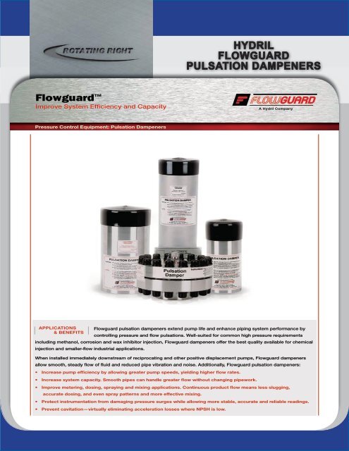
- Hydril Pulsation Dampener Manual Valve
- Hydril K20 Pulsation Dampener Manual Pdf
- Hydril K20 Pulsation Dampener Manual
SFU Series
- SFU o-ring
- SFU wing nut
- Dust cap
- Loading valve
- Bleeder valve
- Cartridge
- Case
SFV & SFVM Series
- 6″ or 8″ suction gasket
- 6″ or 8″ grooved coupling
- Dust cap
- Loading valve
- Bleeder valve
- Cartridge
- Case
SFT Series
/is2.ecplaza.com/ecplaza2/products/a/ae/ae8/1099030334/4355288.jpg)

Installation and Operation Manual Chargeable Dampener Models Dampeners are pressure vessels containing a flexible bladder or bellows inside that separates an inert pressurized gas (air or Nitrogen) from a system fluid in the lower chamber. Depending on how dampeners are configured, they are used as Pulsation Dampeners, Inlet Stabilizers. Recommended location for the pulsation control equipment is within 6 times the nominal pipe diameter of the pump discharge manifold. Discharge damp-eners are not effective when installed away from the pump. M20-7500 (Pneumatic Discharge Dampener with Nitrogen Charge) The 20 gallon pneumatic discharge dampener has been the drilling industry.
- HPG-1 gasket (Nitrile or EPDM)
- Dust cap
- Loading valve
- Bleeder valve
- Cartridge
- Case
SFM Series
- SFM o-rings (2 required)
- SFM wingnut
- Dust cap
- Loading valve
- Bleeder valve
- Cartridge
- Case
- SFM wingnut screw

Hydril Pulsation Dampener Manual Valve
CHARGE TO 80%- 90% OF SUCTION PRESSURE OR THE MAXIMUM CHARGE PRESSURE OF THE CARTRIDGE, WHICHEVER IS LESS. THIS IS ONLY AN APPROXIMATION.
(YOU MAY FIND IT NECESSARY TO DECREASE THE PRESSURE IN THE SUCTION CARTRIDGE TO ACHIEVE OPTIMUM PUMP PERFORMANCE.)
- Shut down pump and relieve line pressure from discharge side before closing suction valve. After discharge line is relieved of pressure, close suction line valve and drain suction line.
- Open bleeder valve ’A’.
- Remove loading valve protector cap ’B’.
- Remove cap from loading valve ’C’.
- Loosen safety nut ’D’ three full turns.
- Using NITROGEN ONLY, charge the cartridge through loading valve ’C’ to the recommended operating pressure (90% of suction pressure). (DO NOT EXCEED MAXIMUM CARTRIDGE CHARGE PRESSURE).
- Tighten safety nut ’D’ on loading valve ’C’.
- Replace loading valve protector cap ’B’
- Open suction valve. When air from bleeder valve ’A’ is evacuated, close bleeder valve ’A’.
Hydril K20 Pulsation Dampener Manual Pdf
- Shut down pump and relieve line pressure.
- Open bleeder valve ’A’.
- Remove loading valve protector cap ’B’.
- Remove cap from loading valve ’C’.
- Loosen safety nut ’D’ three full turns.
- Using NITROGEN ONLY charge the cartridge through loading valve ’C’ to correct charge pressure (use chart below).
NOTE: DO NOT EXCEED MAXIMUM CARTRIDGE CHARGE PRESSURE (ON CASE LABEL). - Tighten safety nut ’D’ on loading valve ’C’ and replace cap.
- Replace loading valve protector cap ’B’.
- Open suction valve. When air from bleeder valve ’A’ is evacuated, close bleeder valve ’A’.
WARNING
Hydril K20 Pulsation Dampener Manual
THE USE OF ANY GAS OTHER THAN NITROGEN IS EXTREMELY DANGEROUS.
NEVER ATTEMPT TO CHARGE OR PRE-CHARGE A CARTRIDGE OUTSIDE OF THE PULSATION STABILIZER CASE.
FOR PROPER CHARGING PROCEDURES REFER TO THE SUCTION OR DISCHARGE CHARGING GUIDE.